Laser Processing of 3M™ Flux Field Directional Material EM15TF
Laser Processing of 3M™ Flux Field Directional Material EM15TF
Introduction
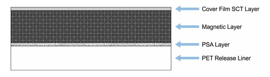
3M™ Flux Field Directional Material (FFDM) EM15TF is part of the product line of similar materials referred to as 3M Flux Field Directional Materials including EM15TF-007, -008, -010, -012, -014, -020, -026, and -026-H. EM15TF-012 was selected for testing compatibility with laser processing and consists of a 10µm thick black PET single-coated tape (SCT) cover film, a 100µm thick sintered ferrite magnetic layer, a 10µm thick pressure sensitive adhesive (PSA) layer, and a 75µm thick PET release liner. A diagram depicting the layers of the EM15TF material is shown in Figure 1.
Figure 1. FFDM EM15TF diagram showing the order of the SCT layer (10µm), magnetic layer (100µm), PSA layer (10µm), and PET release liner (75µm).
3M FFDM materials are flexible magnetic sheets used as magnetic shielding for radio frequency (RF) applications. The rigid, brittle nature of the internal sintered ferrite magnetic layer makes this material difficult to process, resulting in cracking and rough edges when processed with conventional mechanical methods. The non-contact nature of laser processing overcomes this difficulty and allows applications with fine geometry to be processed without excessive material deformation or cracking. 3M FFDM materials are only suitable for laser cutting, which produces smooth cut edges and minimal heat-affected zones without degrading the physical properties of the materials. Other laser processes are not suggested as they are not conducive to the intended use of these materials. Universal Laser Systems makes it simple to consistently and repeatedly process these materials to a high degree of dimensional accuracy because the non-contact nature of laser cutting greatly reduces cracking during processing.
Laser Processing Notes
3M FFDM EM15TF was tested to assess laser processing compatibility and determine the best configuration of laser peak power and wavelength. The inorganic nature of the sintered ferrite layer requires the use of the MultiWave Hybrid™ system configuration that combines a 1.06µm fiber laser and a CO2 laser into one simultaneous processing beam, producing a consistent edge with minimal heat affect. The 1.06µm laser is efficiently absorbed by the sintered ferrite, scoring the material without cracking it. The addition of the 9.3 or 10.6µm laser energy in a simultaneous beam heats the sintered ferrite as it is scored, causing controlled crack propagation along the score line. Without the use of the MultiWave Hybrid configuration, the 1.06µm wavelength alone only scores the material but does not produce the controlled cracking that separates the material along the lasers path, and the 9.3µm or 10.6µm laser energy alone will not affect the sintered ferrite material. The remaining three layers of SCT, PSA, and PET readily absorb either the 9.3 or 10.6µm wavelengths and are processed simultaneously with the sintered ferrite layer. With an optimal configuration of 75 watts of 9.3µm or 10.6µm laser energy and 50 watts of 1.06µm laser energy, laser cutting of 3M FFDM EM15TF with the release liner in place produces a consistent edge. Microscopy images taken at 300x magnification of the top and bottom side of the edge after laser cutting the EM15TF are shown in Figures 2 and 3, respectively.
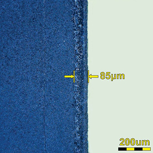
Figure 2. Microscopy image (300x) of the laser cut edge of 3M FFDM EM15TF shown from the SCT layer (top side). The heat-affected zone measures 85µm.
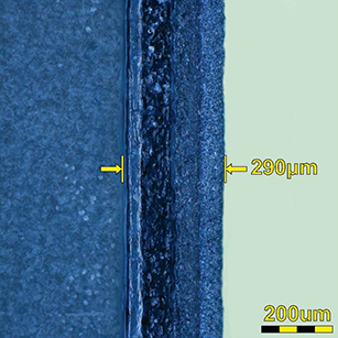
Figure 3. Microscopy image (300x) of the laser cut edge of 3M FFDM EM15TF shown from the PET release liner (bottom side). The heat- affected zone measures 290µm.
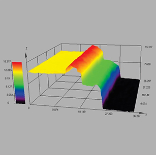
Further inspection shows that the black PET SCT layer and the PET release liner are cleanly processed by the 9.3µm or 10.6µm CO2 laser source. The sintered ferrite magnetic layer is cleanly processed by the 50 watt 1.06µm laser source combined with either the 9.3 or 10.6µm CO2 laser source using the MultiWave Hybrid configuration. In Figure 4, the contour of the laser-processed edge of 3M FFDM EM15TF is depicted in a 3D image, illustrating how the PET layer reacts to the laser energy by forming a “wave” of melted material along the top surface of the cut edge (red area).
Figure 4. 3D microscopy image (300x) of the laser-processed edge of 3M FFDM EM15TF shown from the PET layer (bottom side).
Processing Example
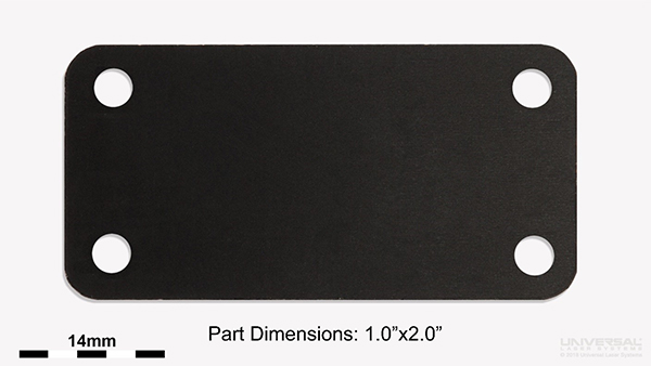
3M FFDM EM15TF adhesive tape applications that require fine geometry and intricate detail without degrading the physical properties of the material can be accomplished with Universal Laser Systems technology. An example demonstrating the results of laser cutting 3M FFDM EM15TF material is shown in Figure 5.
Figure 5. Example of the fine geometry possible with laser cutting of 3M FFDM EM15TF.
Conclusion
3M FFDM EM15TF is suitable for laser processing and was extensively tested to determine the optimal processing configuration. Through this testing it was determined that laser cutting is a viable process. A 75 watt 10.6µm or 9.3µm CO2 laser source combined with the 50 watt 1.06µm fiber laser source using MultiWave Hybrid technology is the ideal configuration for laser cutting this material. The sintered ferrite layer efficiently absorbs the 1.06µm combined with 10.6 or 9.3µm wavelength laser energy and the SCT, PSA, and PET layers efficiently absorb the 10.6 or 9.3µm wavelengths to produce a clean smooth edge that has a minimal heat-affected zone and discoloration.