Laser Processing of Thermally Conductive Materials
This summary is adapted from original Universal Laser Systems processing reports for selected thermally conductive pads, interface tapes, adhesive transfer tapes, and heat-spreading materials.
Thermally conductive pads and tapes are often selected because they manage heat, conform to uneven surfaces, and support compact electronic assemblies.
Those same material properties can make conventional conversion methods more difficult when the application requires fine geometry, narrow channels, small openings, or clean edge quality.
Across the thermally conductive materials highlighted here, the original ULS reports show a consistent pattern: laser processing enables detailed part geometry while reducing mechanical deformation and supporting repeatable dimensional control.
Why these materials matter
Thermally conductive interface materials appear in electronics, power systems, battery assemblies, LED products, communications hardware, and other designs where heat must move efficiently away from components.
Typical constructions include silicone interface pads, acrylic interface pads, adhesive transfer tapes filled with conductive ceramic particles, interface tapes with PET carriers, and copper-based heat-spreading tapes.
From a converting standpoint, the challenge is not only separating the material. The challenge is doing it cleanly while preserving function, limiting distortion, and supporting part-to-part consistency.
3M™ Thermally Conductive Silicone Interface Pad 5519
Ceramic-filled silicone pad with PET liners
The original 5519 report describes a conformable silicone interface pad filled with thermally conductive ceramic particles and protected by PET liners on both sides. ULS testing documented that a combined 9.3 µm CO2 and 1.06 µm fiber MultiWave Hybrid™ configuration produced smooth processed edges with minimal heat effects, while the PET liners absorbed much of the visible heat impact.
- Documented best configuration in the original report: dual 75 watt 9.3 µm CO2 sources combined with a 50 watt 1.06 µm fiber source in MultiWave Hybrid™ configuration.
- Reported benefit: clean edge quality with minimal heat-affected zone on the silicone layer itself.
- Practical implication: suitable where soft, liner-protected thermal pads need detailed conversion without mechanical distortion.
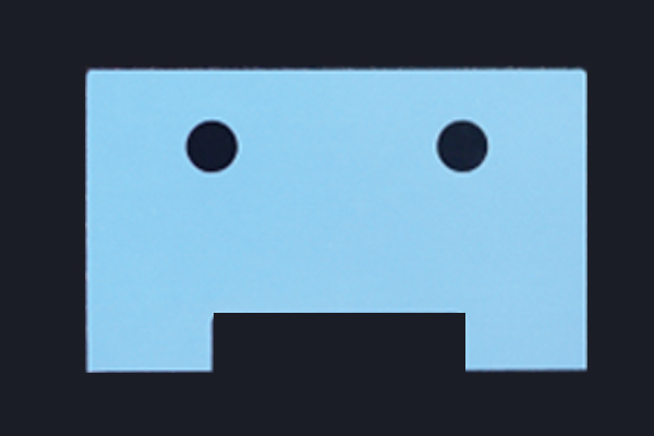
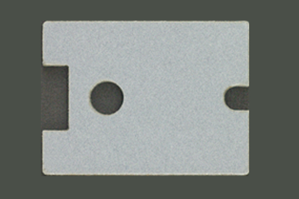 Fine-geometry sample from the original ULS 5519 report.
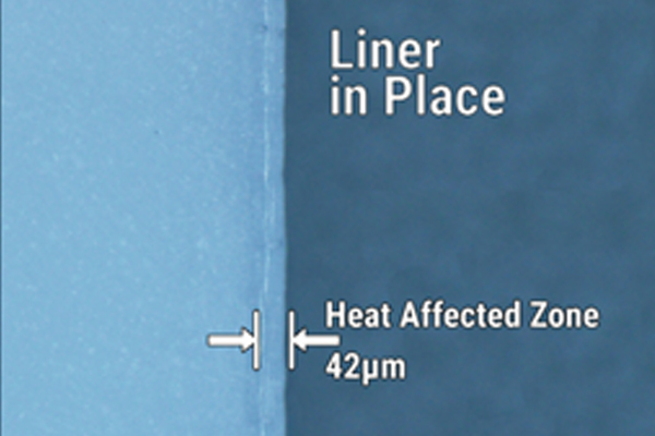
 Microscopy view from the original ULS 5519 report showing the processed edge with liner in place.
3M™ Thermally Conductive Acrylic Interface Pad 5550H
Ultra-soft acrylic interface pad with PET liner protection
The original 5550H report describes a highly conformable acrylic thermal pad designed to transfer heat while wetting out to uneven surfaces. Because the material is delicate, the report emphasizes the value of non-contact processing. ULS testing documented that 9.3 µm CO2 processing delivered a clean edge with minimal visible heat effects.
- Documented best configuration in the original report: 75 watt 9.3 µm CO2.
- Reported benefit: the ceramic-filled acrylic pad was visually free of significant heat effects in the microscopy image shown in the report.
- Practical implication: useful where ultra-soft thermal pads must be converted into precise shapes without deformation from die contact or blade pressure.
 Fine-geometry sample from the original ULS 5550H report.
 Microscopy view from the original ULS 5550H report.
3M™ Thermally Conductive Adhesive Transfer Tape 8810
Thin thermal adhesive transfer tape with PET liners
The original 8810 report presents a thermally conductive adhesive transfer tape intended to create a preferential heat-transfer path between components and heat sinks or other cooling devices. ULS testing documented strong 9.3 µm absorption by both the acrylate adhesive layer and PET liners, enabling detailed processing with small heat-affected zones.
- Documented best configuration in the original report: 30 watt 9.3 µm CO2.
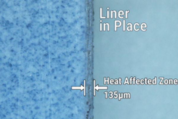
- Reported benefit: microscopy in the source report shows a 42 µm heat-affected zone with the liners in place and 19 µm with liners removed.
- Practical implication: good fit for thin thermal adhesive parts that need intricate detail and consistent repeatability.
 Sample geometry from the original ULS 8810 report.
 Microscopy view from the original ULS 8810 report with liner in place.
3M™ Thermally Conductive Interface Tape 8926
Ceramic-filled acrylic interface tape with PET carrier
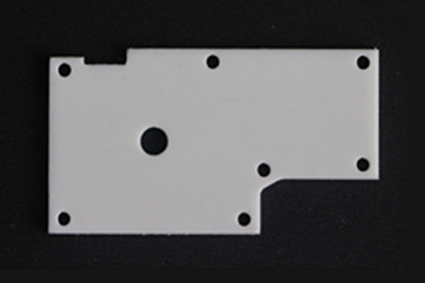
The original 8926 report describes a thermally conductive interface tape intended for heat management and bonding in electronic products. ULS testing documented that the acrylic layer and PET liner both responded efficiently to 9.3 µm energy, supporting clean processing with minimal heat effects.
- Documented best configuration in the original report: 50 watt 9.3 µm CO2.
- Reported benefit: minimal visible heat effects and discoloration in the microscopy image shown in the report.
- Practical implication: useful where thermal interface tapes must be converted into accurate shapes for assembly-friendly handling and fit.
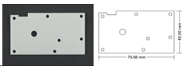 Sample geometry from the original ULS 8926 report.
 Microscopy view from the original ULS 8926 report.
3M™ Thermally Conductive Heat Spreading Tape 9876-15
Copper-based heat spreading tape with polymeric top coat
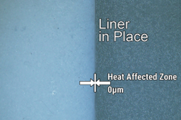
The original 9876-15 report is distinct from the others because the construction includes a thermally conductive copper base foil with adhesive and liner layers. ULS testing documented that 1.06 µm fiber energy transmitted through the clear top coat and was absorbed by the underlying copper foil, making fiber processing the strongest reported configuration for this construction.
- Documented best configuration in the original report: 50 watt 1.06 µm fiber.
- Reported benefit: clean processed edges across the layered construction with minimal heat-affected zone.
- Practical implication: especially relevant where a heat-spreading copper layer must be converted with detail while maintaining overall part integrity.
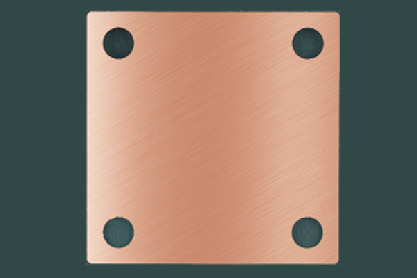 Sample geometry from the original ULS 9876-15 report.
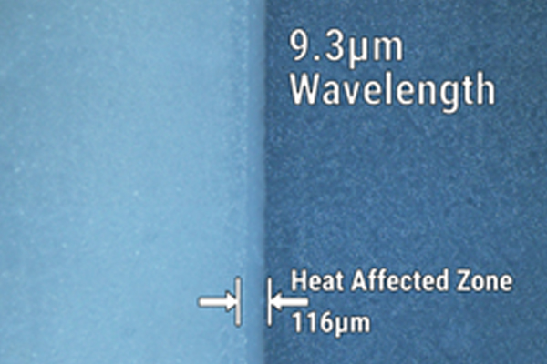
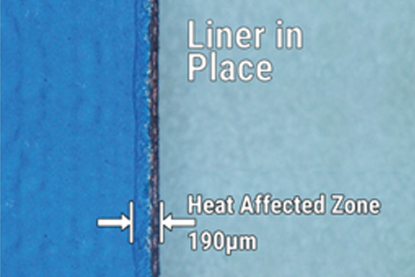 Microscopy view from the original ULS 9876-15 report with liner in place.
Common themes across the source reports
- Fine geometry and intricate detail are emphasized repeatedly across the original reports.
- The non-contact nature of laser processing is presented as an advantage for soft, delicate, or highly conformable thermal materials.
- Heat effects are managed not only by power selection, but by matching wavelength to the dominant absorbing layers in the material stack.
- Liners frequently absorb a visible portion of the heat impact, helping protect the working material layer beneath.
Frequently asked questions
Why use laser processing for thermally conductive materials instead of mechanical converting?
Soft pads, transfer tapes, and interface tapes can deform under contact methods. Laser processing removes the tool-contact variable and can support fine detail, narrow features, and repeatable edge quality.
Is one laser wavelength best for every thermally conductive material?
No. The source reports show that material construction matters. Acrylic- and PET-based constructions in this set often favor 9.3 µm CO2 processing, while the copper-based 9876-15 construction favors 1.06 µm fiber processing. The 5519 silicone pad performed best in the documented MultiWave Hybrid™ configuration.
Why do liners matter so much in these reports?
Liners are part of the process stack. In several source reports, the liner absorbs or contains a meaningful portion of the visible heat effects, which can help preserve the appearance and condition of the active thermal layer.
Can these materials support detailed part geometry?
That is one of the main conclusions highlighted throughout the source reports. The examples repeatedly show small features and detailed part outlines that would be more difficult to achieve consistently with contact-based methods.
What kinds of products may use these materials?
The source reports describe applications related to electronics cooling, thermal interface management, heat spreading, and bonding within assemblies where heat must move away from components.
Related ULS resources (links)
Explore the broader ULS material resources and original report library: Laser Material Processing Reports
Search materials and categories in the ULS materials library: Materials Library
Learn more about working with ULS on material evaluation:
Application Testing
Source credits (links)
This document adapts and synthesizes information and figures from original Universal Laser Systems material processing reports. Original report titles:
- Laser Processing of 3M™ Thermally Conductive Silicone Interface Pad 5519
- Laser Processing of 3M™ Thermally Conductive Acrylic Interface Pad 5550H
- Laser Processing of 3M™ Thermally Conductive Adhesive Transfer Tape 8810
- Laser Processing of 3M™ Thermally Conductive Interface Tape 8926
- Laser Processing of 3M™ Thermally Conductive Heat Spreading Tape 9876-15